
Today, I would like to share my experience with custom views, and hopefully this can help someone to create their own custom view. The custom view here is a simple analog clock, which is an analog clock view that can be put in XML to show it. Here is the sample
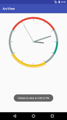
It’s available in github and everyone can take a look
https://github.com/huteri/analogclock
Let’s see how I created this custom view
1. Canvas.drawArc()
Canvas.drawArc() is a function from Canvas API. The basic functionality of this api is to draw arc and we can use this to draw complete circle.
1
2
drawArc(RectF oval, float startAngle, float sweepAngle, boolean useCenter, Paint paint)
// Draw the specified arc, which will be scaled to fit inside the specified oval.
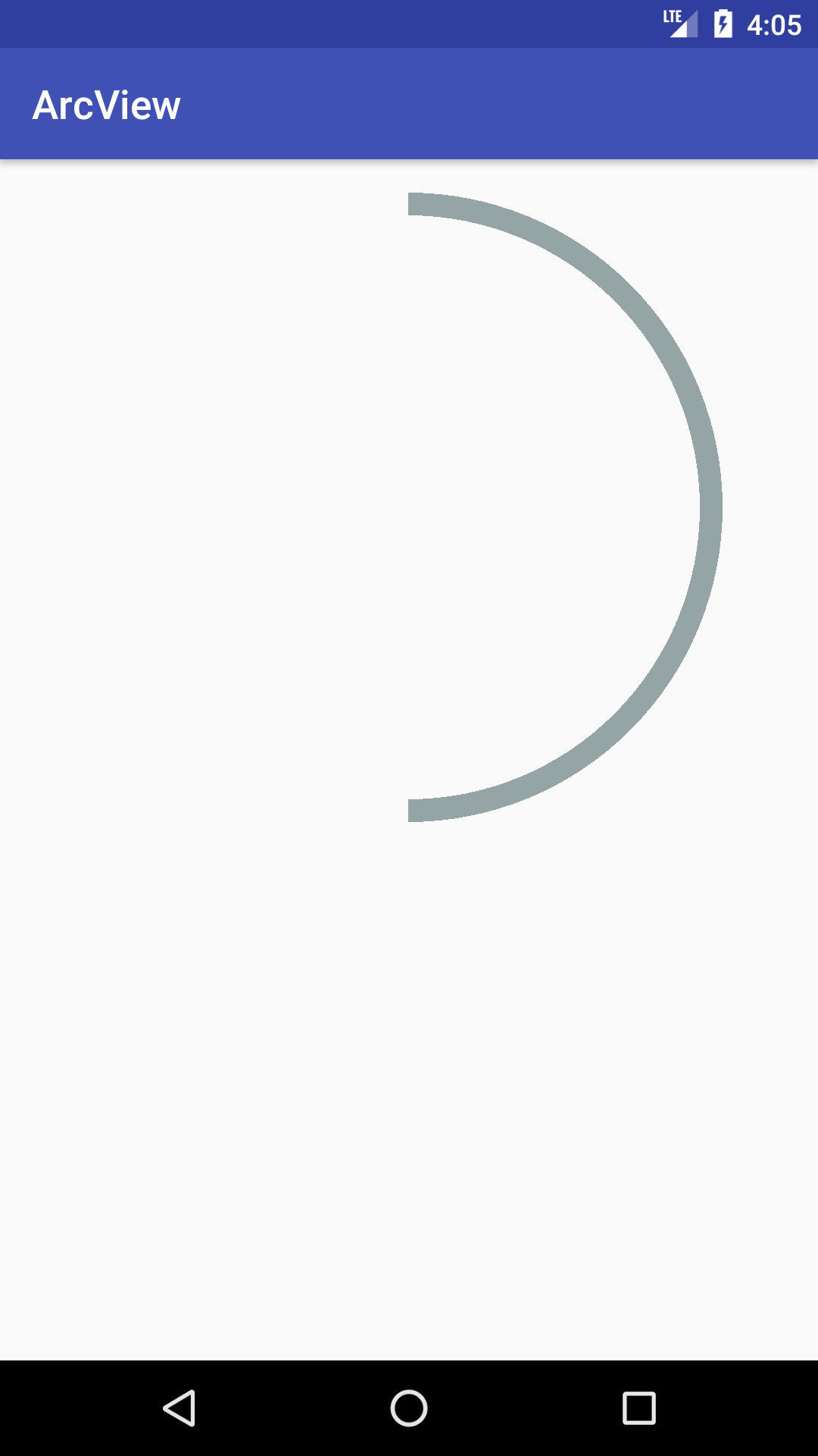
Basically, the startAngle is starting point to draw the arc which starts from 3 o’clock and sweepAngle is how long the arc will be so if we set -90 as startAngle, and 180 as sweepAngle, then android will draw half oval from 12 o’clock to 6 o’clock.
So, what is RectF in this case? It’s like the canvas where we want to draw the circle. The arc will follow the form of this rectF, so to draw a circle we need the canvas to be a square which has 4 equal sides.
1
2
3
4
5
6
7
8
9
rectF.apply {
	set(centerX - 400, centerY - 400, centerX + 400, centerY + 400)
}

it.drawArc(rectF, -90f, 180f, false, paint.apply {
	color = Color.parseColor("#95a5a6")
	strokeWidth = 20f
	style = Paint.Style.STROKE
})
In the code above, we create a rectF and set the size to be 400 in all 4 sides, then we can draw an arc inside of this rectF
2. Draw Moving Hands in Analog Clock
We have moving hands in the analog clock for hour, minute, and second. How to draw this? Basically the hands are just rectangular with rounded corners. We can draw rounded rectangular easily with Canvas.drawRoundRect() api but how do we draw rounded rect to point to 5 o’clock? This is where Canvas.save() and Canvas.rotate() come to play.
First we save the snapshot of the current canvas with Canvas.save(). I would say this saves the position of each view inside of the current canvas.
Second we draw the rounded rectangular to point to 12 o’clock, then rotate the canvas 150 degrees to get it to 5 o’clock. (every hour is 30 degree)
Call Canvas.restore to restore position of each view from last save. it won’t restore the position of the rounded rectangle and its rotation because we called ‘Canvas.save’ before we drew these.
3. Touch Area and Selected Area
This is one the hardest part in this custom view. It’s about how to make our custom view clickable and give feedback to our touches.
So, how do we define touch area for specific view? By using Region. Defining a region is basically the same like we draw a view. We can use the arc as the region, but we should make the region in such way that the user can easily touch and select the item.
That’s why we need Path instead of only an arc, because with Path we can define the touch area we want instead of just an arc.
Look on the screenshot for custom view again, we want to make sure that user can easily select the data. So we are going to make touch area from the center of the view to arc. It’s like slice of pizza. Here is to give you picture.
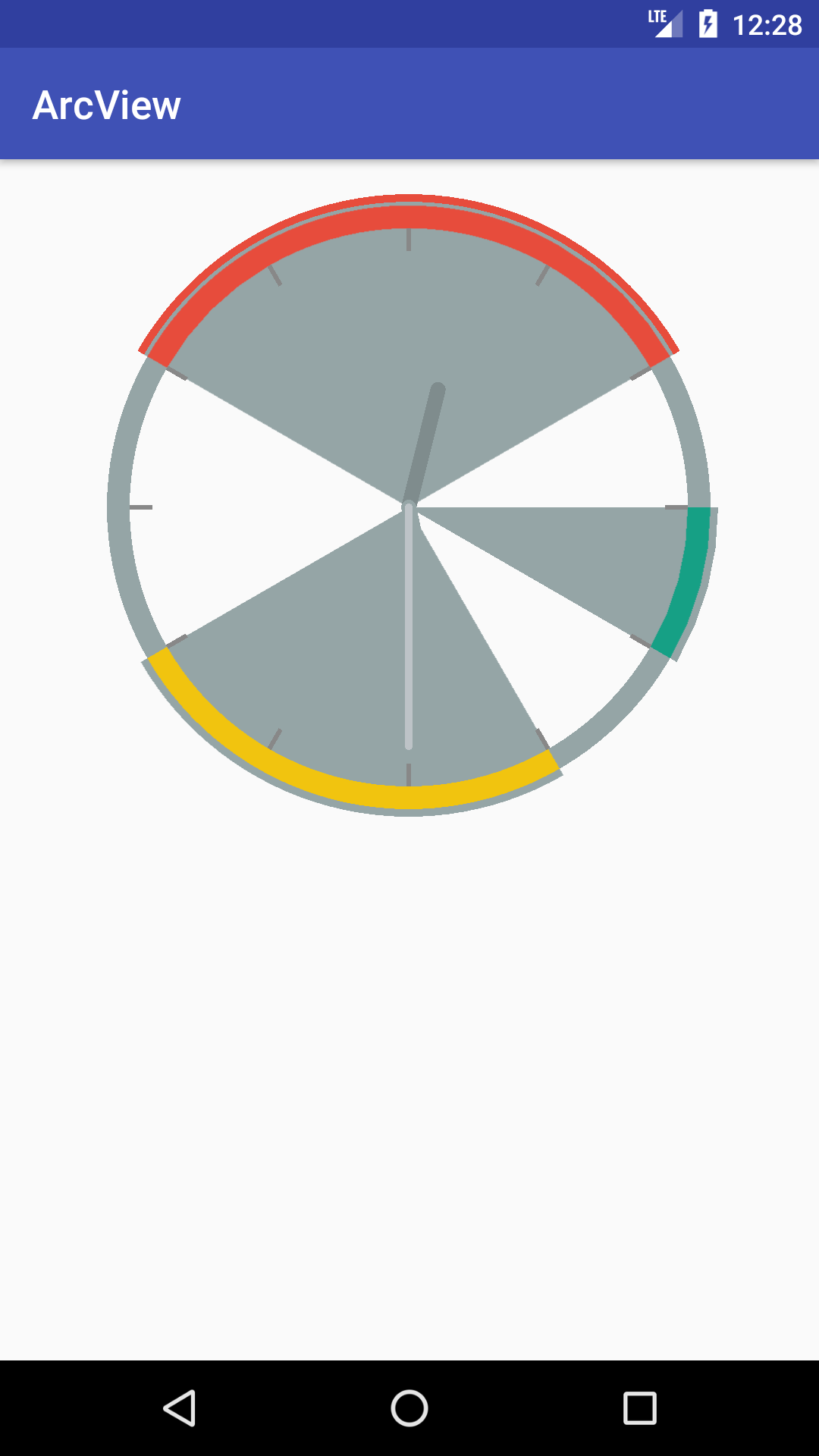
The slices with grey background are the touch area, so whenever user touches inside of this area, the item will be selected.
Remember, in order to define touch area, we need to know how to draw it. Let’s see how we can define this area.
1
2
3
4
5
6
7
8
9
10
11
12
13
14
15
16
17
18
19
val centerX = (it.width.div(2)).toFloat()
val centerY = (it.height.div(2)).toFloat()

var pathSelected = Path()

rectFSelected.apply {
    set(centerX - 400, centerY - 400, centerX + 400, centerY + 400)
}

pathSelected.arcTo(rectFSelected, startAngle, sweepAngle)

rectFSelected.apply {
    set(centerX, centerY, centerX, centerY)
}

pathSelected.arcTo(rectFSelected, 0f, 0f)
pathSelected.close()

pathSelected.computeBounds(rectFSelected, true)
First, we are going to define the first arc which is the curve of the slice, and then define the second arc, but if you look closely, the rect for second arc is the center of the view which is height and width of the canvas divided by 2. So there is actually no arc. It’s just telling path to use this center view. Path.close() will close those 2 arcs with lines. That’s how we get the slice of the pie.
That’s it. we get the Path and then we only need to set this path as region, and put it inside of the data list.
Override onTouchEvent() then we check whether the touch point is inside of one of the regions, then call sliceClickListener callback then call postInvalidate() to draw the selected area.
1
2
3
4
5
6
7
8
9
10
11
12
13
14
15
16
17
18
19
20
21
22
23
24
25
26
27
28
29
30
 override fun onTouchEvent(event: MotionEvent?): Boolean {

    var point = Point()
    point.x = event!!.x.toInt()
    point.y = event!!.y.toInt()

    var count = 0

    for (arcSlice in list) {
        var region = Region().apply {
            setPath(arcSlice.path, arcSlice.region)
        }

        if (region.contains(point.x, point.y) && event.action == MotionEvent.ACTION_DOWN) {
            indexSelected = count

            onSliceClickListener?.onSliceClick(indexSelected)
            break
        }

        count++

    }

    if (event.action == MotionEvent.ACTION_DOWN || event.action == MotionEvent.ACTION_UP) {
        postInvalidate()
    }

    return true
}
Comments powered by Disqus.